VIBRATION ABSORBERS
- model :
- Vibration Absorbers
Nominal pressure : PN 35 up to diameter 54 and PN 25 from diameter 64
Temperature : -100 ºC min + 250 ºC max
Fluid : suitable for group 2 according to art. 9 Directive 97/23/EC (P.E.D.)
Product Description
TECHNICAL SHEET
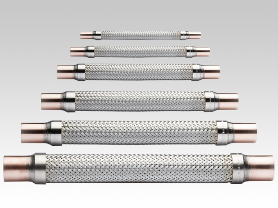
Available Dimensions
| mm | inch | A | B | C | D | E | ND | Item |
| 6 | 1/4″ | 6,6 +/- 0,2 | 1,0 | 20 | 19 | 230 +/-5 | 10 | 1 |
| 8 | / | 8,2 +/- 0,2 | 1,0 | 20 | 19 | 230 +/-5 | 10 | 2 |
| / | 3/8″ | 9,7 -0,1+ 0,3 | 1,0 | 20 | 19 | 230 +/-5 | 10 | 3 |
| 10 | / | 10,2 -0,1+ 0,3 | 1,0 | 20 | 19 | 230 +/-5 | 10 | 4 |
| 12 | / | 12,2 -0,1+ 0,3 | 1,0 | 20 | 21 | 230 +/-5 | 12 | 5 |
| / | 1/2″ | 12,9 -0,1+ 0,3 | 1,0 | 20 | 21 | 230 +/-5 | 12 | 6 |
| 15 | / | 15,2 -0,1+ 0,3 | 1,0 | 25 | 27 | 255 +/-5 | 16 | 7 |
| 16 | 5/8″ | 16,2 -0,1+ 0,3 | 1,0 | 25 | 27 | 255 +/-5 | 16 | 8 |
| 18 | / | 18,2 -0,1+ 0,3 | 1,0 | 25 | 27 | 255 +/-5 | 16 | 9 |
| / | 3/4″ | 19,3 -0,1+ 0,3 | 1,0 | 25 | 27 | 255 +/-5 | 16 | 10 |
| 22 | 7/8″ | 22,4 -0,1+ 0,3 | 1,5 | 25 | 32 | 290 +/-5 | 20 | 11 |
| 28 | 1 1/8″ | 28,9 -0,1+ 0,3 | 1,5 | 25 | 39 | 330 +/-5 | 25 | 12 |
| 35 | 1 3/8″ | 35,3 -0,1+ 0,3 | 2,0 | 30 | 48 | 375 +/-10 | 32 | 13 |
| 42 | 1 5/8″ | 42,3 -0,1+ 0,3 | 2,0 | 35 | 58 | 430 +/-10 | 40 | 14 |
| 54 | 2 1/8″ | 54,3 -0,1+ 0,3 | 2,5 | 45 | 70 | 510 +/-10 | 50 | 15 |
| 64 | / | 64,4 -0,1+ 0,4 | 2,5 | 50 | 89 | 690 +/-10 | 65 | 16 |
| 65 | / | 65,4 -0,1+ 0,4 | 2,5 | 60 | 89 | 690 +/-10 | 65 | 17 |
| 67 | 2 5/8″ | 67,1 -0,1+ 0,4 | 3,0 | 60 | 89 | 690 +/-10 | 65 | 18 |
| 76 | 3″ | 76,4 -0,1+ 0,4 | 3,0 | 60 | 89 | 690 +/-10 | 65 | 19 |
| 80 | / | 80,5 -0,3 +0,5 | 3,0 | 80 | 89 | 690 +/-10 | 65 | 20 |
| / | 3 1/8″ | 79,8 -0,2+0,4 | 3,0 | 80 | 89 | 690 +/-10 | 65 | 21 |
| 89 | 3 1/2″ | 90,0 -0,3+0,5 | 3,0 | 80 | 104 | 710 +/-10 | 80 | 22 |
| / | 3 5/8″ | 93,0 -0,3+0,5 | 3,0 | 90 | 104 | 710 +/-10 | 80 | 23 |
| ND = Nominal Diameter of the flexible hose | ||||||||
COMPONENTS
1. End fitting mat: Cu DHP (EN 12449 Cu DHP)
2. Fitting mat: AISI 303/304 (EN 10088-1 1.4305/1.4301)
3. Braid mat: AISI 304 (EN 10088-1 1.4301)
4. Flexible pipe mat: AISI 321/316L (EN 10088-1 1.4541/1.4404)
5. Ring mat: AISI 304 (EN 10088-1 1.4301)
NORMAL WORKING CONDITIONS
Nominal pressure : PN 35 up to diameter 54 and PN 25 from diameter 64
Temperature : -100 ºC min + 250 ºC max
Fluid : suitable for group 2 according to art. 9 Directive 97/23/EC (P.E.D.)
CONSTRUCTION
Manifacturing in accordance to Directive 97/23 /EC (P.E.D.) requirements. Lett vibration absorber is made from stainless steel with copper DHP end fittings. All weldings, included copper/stainless steel, are made by TIG or laser systems.
Being brazing-free, it is possible to braze the end fittings to the pipe system without any overheating risk to the lett itself.
EMPLOY
Lett vibration absorber is used to avoid the vibrations induced by the compressor. It also reduces noises and can compensate smaller inner displacments. Furthermore, its unique speciality allows vertical installation too. The possibility of water condensation in the lower side has been eliminated, therefore, no problem even at temperatures below 32 ºF (0 ºC).
INSTALLATION
User must be aware that lett cannot absorb torsional and axial stresses, either in compression and extension.
Lett must be installed in perpendicular to the vibration flow. In certain cases it is necessary to assemble two lett to ensure good performances to fatigue life. Should this be the case, a suitable spring support must be placed to ensure stability (see sketch below). Fluid overflow inside lett can set off turbolences and noises that can damage and reduce its fatigue life. If so, it is highly recommended to switch to a bigger lett size.
The connection between lett and the pipe system is usually made by brazing. Lett unique special characteristics enable the fitter to perform such operations care-free from any overheating to the lett itself.
Lett test pressure must not exceed the nominal pressure x 1.5.
CORROSION PERFORMANCES
The materials of which lett is made fully suit the conveyed fluids, therefore no extra thickness is needed. Installer needs to pay special attention to protect lett from the environment corrosion factors
DISASSEMBLY
When you need to take down a lett – Cut the lett with a handsaw and not by flame cutting. make sure all the following steps are followed:
Drain all fluids from the piping system;
Clean the inside of the piping sytem;
Cut the lett with a handsaw and not by flame cutting.
MARKING
According to Directive 97/23/EC (P.E.D.), lett is marked as follows:
Item 001 to 013 : 7577/XXX-PN 35-MM/AA (XXX = position on the drawing table)
Item 014 to 015 : 7577/XXX-PN 35/LLLL/AA ( MM = manufacturing month)
Item 016 to 032 : 7577/XXX-PN 25/LLLL/AA ( AA = manufacturing year)
(LLLL = identification lot number)
Lett may be marked in any of the “MARKING” areas in the drawing.
For the American market: UL certification available on request.
COMPARISON WITH SIMILAR PRODUCTS
WHAT MAKES LETT SO UNIQUE?
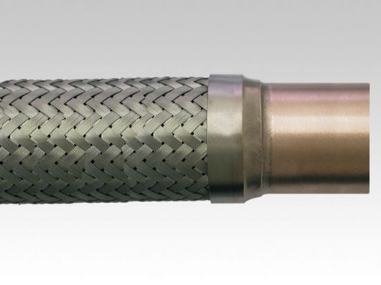
Lett’s copper ends are welded (TIG method) to the flexible hose, while other manufacturers braze them. Brazing unites metal by means of an alloy, generally on a silver base, with a fusion temperature ranging from 1292ºF to 1562ºF.
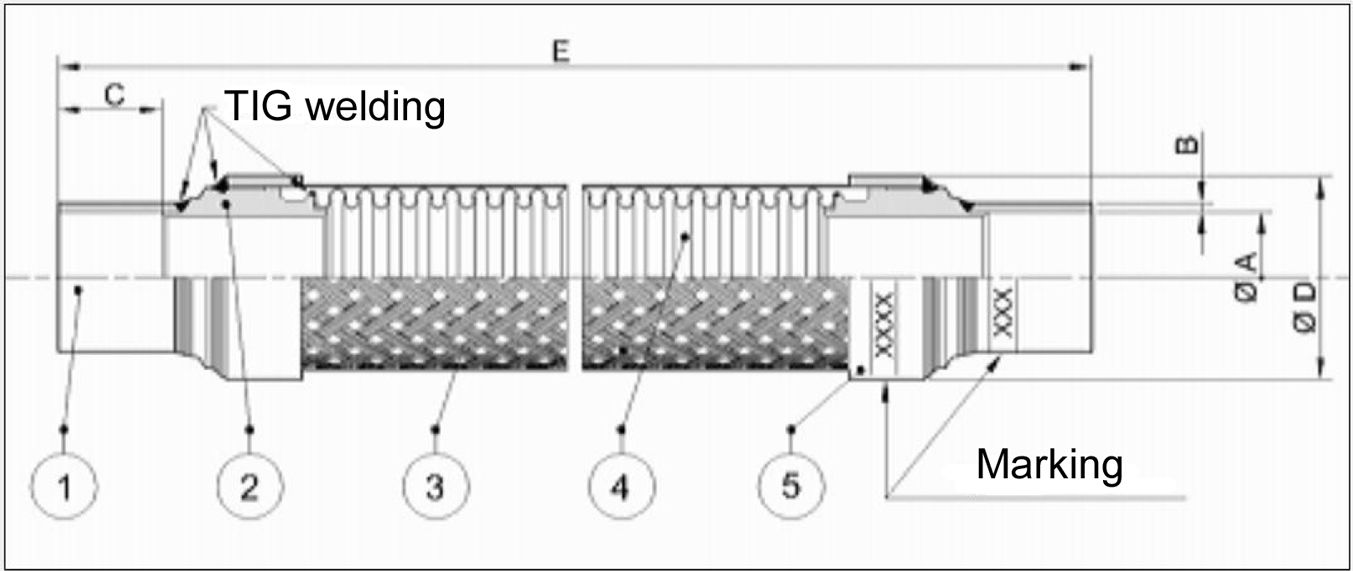
Here’s how lett is welded:
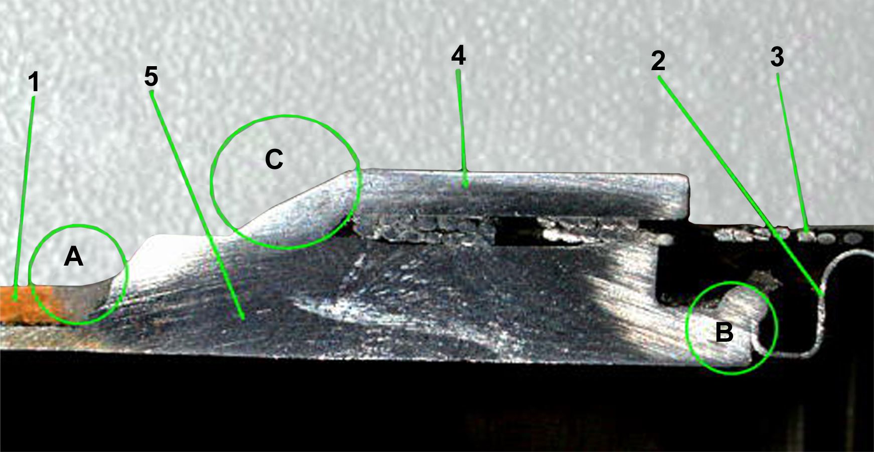
Part # 1 is the copper end,
Part # 2 is the flexible hose,
Part # 3 is the braiding,
Part # 4 is the ferrule,
Part # 5 is the transition ring in stainless steel.
Marked A (the first welding), unites the copper end to the transition ring;
Marked B (the second welding), unites the transition ring to the flexible hose;
Marked C (the third welding), unites the braid and the ferrule to the transition ring.
All weldings are performed in TIG or laser within argon protected environment.
WHAT IS THE DIFFERENCE THEN?
Instead, other manufacturers braze the vibration absorber. This is how they normally do:
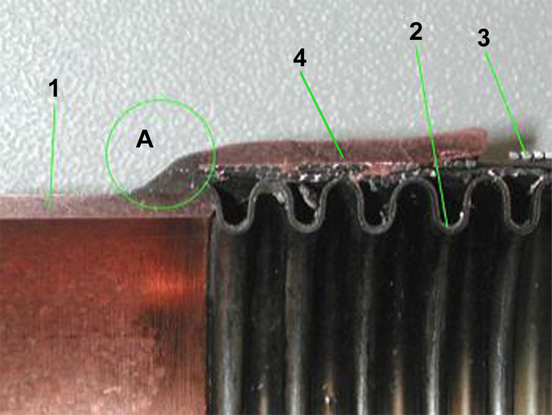
Part # 1 is the copper end,
Part # 2 is the flexible hose,
Part # 3 is the braiding,
Part # 4 is the ferrule.
Marked A (the brazing), unites the different parts by means of an alloy.
This construction simplicity may have an economic advantage: there is no need for a transition ring and a single brazing is made instead of three weldings. However, there are negative consequences; the lack of a transition ring may cause serious problems: keep on reading!
WHAT ARE LETT’S MAIN ADVANTAGES?
When it comes to mount the piece, while brazing the vibration absorber to the piping system, there is no need to protect, usually by applying a cloth, the union between the copper end and the flexible hose, even if using phosphorous copper as an alloy. In fact, it is impossible to overheat the TIG weldings and therefore damaging them.
Furthermore, the construction allows a secure vertical mounting of lett. Generally speaking, installing a vibration absorber in cold conditions often creates a layer of frozen condensation on the outside of the hose. When the system is switched off, the ice starts to melt, causing the water to pour down towards the copper end. The construction of other manufacturers allows the water to accumulate between the flexible hose and the ferrule. When the system is restarted, the water will again freeze and increase in volume, possibly causing the implosion of the hose.
Lett is different because there is no such zone in its construction thanks to the transition ring: therefore, no problem ever for vertical installations.
For the American market: UL certification available on request.